- 7ACAF469539AE5BE731ED4CC5FA1B148

Amazon

PROPERTIES AND USES OF SF6 GAS

PROPERTIES OF SF6 GAS: 
SF6 structure
SF6 Structure

Sulfur hexa-fluoride (SF6): Sulfur hexa-fluoride gas is a chemically stable and inert gas (up to 500°C).
It is available in gas form at normal temperature and pressure (NTP) and in liquid form when temperature less than 10°C.The central atom of sulfur hexa-fluoride gas is sulfur atom and surrounded by six fluorine atom.

The properties of Sulfur hexa-fluoride (SF6) is given below:
  • Its density is five times higher than air.
  • It is non-inflamable.
  • It is colorless.
  • It is odorless.
  • It is non-poisonous.But it is toxic in impure form.
  • It has high insulating property.
  • It has cooling property.
  • It has high dielectric strength at high pressure.
  • It has arc extinguishing property.
  • It is thermally stable.
  • It has low arc-time constant.So, it extinguish the arc instantly.
  • It has high heat convention property.
Uses of Sulfur hexa-fluoride (SF6): Due to above given properties it is mainly used in electrical equipment.It is used in switch gears, circuit breakers, current transformers, bushing, cables, capacitors etc.It is used for electrical equipment those work on 3.6 KV to 765 KV.

Advantages of Sulfur hexa-fluoride (SF6) gas contain electrical equipment: The advantages of sulfur hexa-fluoride gas contain electric equipment is given below:
  • Compactness: This type of equipment compact in size as compare to other type of equipment ( vacuum, oil, air type etc).Thus it saves the installation land cost.
  • Maintenance free: This type of equipment is maintenance free.Only the visual checking of gas monitoring system of equipment is necessary.
  • Less installation time: Due to compact size.This type of equipment required less installation time in comparison to other type of equipment.Thus it also reduces the installation cost.
  • High safety factor: In this type of equipment all the metal part of the equipment earthed.So, the safety factor of this type of equipment is high.
More information about Earthing in electrical system click on the link.

Disadvantages of Sulfur hexa-fluoride (SF6) gas contain electrical equipment: The disadvantages of sulfur hexa-fluoride gas contain electric equipment is given below:
  • High initial cost: The cost of this type of equipment is higher than other type of equipment.
  • Difficult repairing work: The repairing work of this type of equipment is difficult and it takes long time.
  • Requirement of cleanliness: This type of equipment required more cleanliness.Because due to the dust particle and moisture, flash-over may be occur.
  • Problem of gas procurement: There is lot of difficulties in procuring and storing of Sulfur hexa-fluoride (SF6) gas.
Conclusion: Due to high dielectric strength and non-inflamable property.It is mainly used in electric system.In the world most of the country used SF6 gas contain electric equipment.
 

TYPES OF CIRCUIT BREAKER AND ITS RATING

DIFFERENT TYPES OF CIRCUIT BREAKER AND ITS RATING:

Different type of circuit breaker is given below:

  1. Air circuit breaker (ACB)
  2. Air blast circuit breaker (ABCB)
  3. Water circuit breaker (WCB)
  4. Oil circuit breaker (OCB)
  5. Vacuum circuit breaker (VCB)
  6. Sulfur hexafluoride (SF6) breaker 
We can read the basic principal and working of circuit breaker on clicking this link.

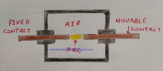
1.Air circuit breaker (acb): In this type of circuit breaker the arc quenching medium is air.
Air circuit breaker
Air circuit breaker

Operation: In this type of circuit breaker, when the circuit breaker operate means contact of circuit breaker separate.Then arc produced between contact.Due to the movable contact of circuit breaker, it increases the arc length.Thus arc suppressed between contact in the presence of arc.
The mechanical life = 5 lac operation
Rating of air circuit breaker: This type of circuit breaker used in both AC and DC.This is used for low voltage (up to 6.6 KV).
Features: The features of air circuit breaker is given below:
  • The installation of air circuit breaker is economical and easy.
  • The design of circuit breaker is very simple.
  • The operation of circuit breaker is easy.
  • The maintenance cost is less.
Drawbacks: The drawbacks of air circuit breaker is given below:
  • It is mainly designed for low voltage.
  • It is used in closed place.
2.Air blast circuit breaker (abcb): In this type of circuit breaker the arc quenching medium is fast blow compressed air between the contacts.
Air blast circuit breaker

Operation: In this type of circuit breaker, when the circuit breaker operate means contact of circuit breaker separate.Then arc produced between contact.Due to fast blow of compressed air between contacts, it suppress the arc between contact.The air blow between contact may be axial, radial or cross blast according to the construction of circuit breaker.The compressed area is collected in a tank and its pressure range is 85 to 175 kg/cm square.
The mechanical life = 5 lac operation
Rating of air blast circuit breaker: This circuit breaker used in the voltage range of 6.6 KV to 400 KV.
Features: The features of air circuit breaker is given below:
  • The operating speed is high.
  • It reduces the risk of fire.
  • The extinguishing of arc easily take place.
  • The maintenance cost is less as compared to oil circuit breaker.
Drawbacks: The drawbacks of air circuit breaker is given below:
  • The air - compressor is require.
  • More possibility of re-striking voltage. 
  • More possibility of over voltage, due to current chopping.
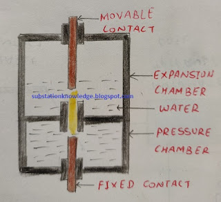
3.Water circuit breaker (wcb): In this type of circuit breaker the arc quenching medium is distilled water.
Water circuit breaker

Operation: In this type of circuit breaker, there are two parts.First is known as pressure chamber in which fixed contact situated.Second is known as pressure chamber in which movable contact situated.When the circuit breaker operate means contact of circuit breaker separate.Then arc and heat produced between contact.This heat vapourise the water and this water vapours increases the pressure in bottom chamber.So, this chamber is known as pressure chamber.
When moving contact move, the vapour comes between the contact and suppress the arc.After extinguishing arc it condense and expand in upper chamber.So, this chamber is known as expansion chamber.
Rating of water circuit breaker: It is used for low voltage (up to 6.6 KV) for low current carrying circuit.
Features: The features of air circuit breaker is given below:
  • It is compact in size as compare to oil circuit breaker for same rating.
Drawbacks: The drawbacks of air circuit breaker is given below:
  • Maintenance cost is high.
  • It is used in low current carrying circuit.
Oil circuit breaker (ocb): In this type of circuit breaker arc quenching medium is oil (dielectric oil, transformer).
We can read the properties of transformer oil on clicking this link.
Oil circuit breaker

Operation: In this type of circuit breaker fixed and movable contact situated in oil tank.When the circuit breaker operate means contact of circuit breaker separate.Then oil comes between these contacts and extinguish the arc and also provide cooling.
Rating of oil circuit breaker: Due to high breaking capacity.This type of circuit breaker used up to 220 KV.
Features: The features of air circuit breaker is given below:
  • The oil provide insulation between contact and tank body.
  • The oil provide cooling.
  • The oil transfer the heat.
  • The cost of oil circuit breaker is less as compared to air circuit breaker.
Drawbacks: The drawbacks of air circuit breaker is given below:
  • The installation and maintenance cost is high.
  • The oil contain moisture at rainy season.Due to this dielectric strength of oil decreases.
  • The testing of oil is necessary after 1 year.
  • Periodically inspection is necessary.
Vacuum circuit breaker (vcb): In this type of circuit breaker the arc is extinguish in vacuum.
Vacuum circuit breaker

Operation: In this type of circuit breaker the fixed and movable contact situated in a chamber.This chamber is known as vacuum interrupter (in which closing or opening of circuit breaker take place).When the circuit breaker operate means contact of circuit breaker separate.Then arc produced between contact is suppress in vacuum interrupter.
The mechanical life = 5 lac operation
Rating of vacuum circuit breaker: The vacuum circuit breaker is mainly used for 11 KV, 33 KV (rms voltage).
Features: The features of air circuit breaker is given below:
  • It is compact in size.
  • It can be operated in open as well as closed place.
  • Less maintenance required.
  • High operating speed.
  • It is more reliable.
  • High making and breaking capacity as comparison to air circuit breaker, oil circuit breaker.
Drawbacks: The drawbacks of air circuit breaker is given below:
  • We cannot check vacuum in interrupter without test.
Sulfur hexa fluoride (SF6) breaker: In this type of circuit breaker arc extinguishing medium is sulfur hexa fluoride gas.
More information about Sulfur hexa fluoride (SF6) gas click on given link.
sf6 breaker
SF6 breaker

Operation: In this type of circuit breaker fixed and movable contact situated in a chamber that is filled with sulfur hexa fluoride gas.When the circuit breaker operate means contact of circuit breaker separate.Then arc produced between contact is suppress by sulfur hexa fluoride gas in chamber.
Rating of vacuum circuit breaker: This circuit breaker is used up to 750 KV.
Features: The features of air circuit breaker is given below:
  • It is compact in size.
  • It can be operated in open as well as closed place.
  • Less maintenance required.
  • High operating speed.
  • It is more reliable.
  • High making and breaking capacity as comparison to air circuit breaker, oil circuit breaker.
Drawbacks: The drawbacks of air circuit breaker is given below:
  • High initial cost.
  • Problem of gas procurement.
  • Difficult repairing work.
Conclusion: The final conclusion is that circuit breaker is necessary for electric circuits.But at the time of selection of circuit breaker, we should keep some point in mind like rating, cost, installation place, type etc.


PERMIT IN ELECTRIC SYSTEM

WHAT IS THE MEANING OF PERMIT ON ELECTRIC EQUIPMENT AND LINES?

PERMIT: Permit in electric system means permission taken for a fix time by authorize person from controlling authority to work on electric equipment and feeders.

OR

Permit on electric system means electric equipment and feeder are in off ( no current flow) position for a fix time and now the feeder and equipment is in safe position to work on it.


WHY AN ELECTRICAL PERMIT IS REQUIRED?

The requirements of permit on electric lines and equipment is given below:

  • At the time of attending breakdown of lines (feeders) at the time of fault.
  • Schedule maintenance of electric equipment and lines.
  • At the time of tree trimming of lines.
  • At the time of attending breakdown of feeder, if another feeder cross the faulty feeder or if both the lines (feeder) on same pole.Then permit is also issue on normal feeder, this permit issue on normal feeder for safety purpose.
  • At the time of preventive maintenance of equipment and lines.
  • For clearing fault of electrical equipment (substation power transformer, circuit breaker etc).
  • Some time for new connection of consumers.
  • Erection of new feeder (safety purpose).

PROCESS OF ISSUING PERMIT: Mainly permit issues by substation staff (substation operator, substation attendant) to field staff.Substation staff issue permit to authorize person of field staff.

Firstly field staff writes the reason of permit on feeder in massage book and also writes the approximate time of completion of work.After this substation staff and field staff fill a permit that follow permit issue process.After filling the permit book, substation staff issue a permit page to the field staff or issue a Permit To Work (PTW) code (permit page number).The given below image shows the permit format.

Permit Page
Permit Page

Following work should be done after issuing written permit:

  • Check the feeder/line circuit breaker panel on which permit issue.
  • Wear the safety dress (helmet, gloves, safety shoes etc).
  • Trip the circuit with the help of TNC (TRIP - NEUTRAL - CLOSE) switch or mechanically by trip push button in circuit breaker trolley.
  • Check the electrical and mechanical indication that shows the breaker in OFF condition.
  • Check the load current in all three phases (R - Y - B) of ammeter.
  • After this Rack out the trolley of circuit breaker and check the circuit breaker position indicator.The circuit breaker position indicator shows the three position of circuit breaker that is given below.
  1. Breaker is in ON position - SERVICE
  2. Breaker is in OFF position - SERVICE/INTERMEDIATE
  3. Trolley is in RACK OUT position - TEST
  • Open the main isolator/G.O. (Gang operated ) switch  of the feeder.It is mainly situated at the first H pole of the feeder near the substation.
  • Put the PTW tag on the circuit breaker panel on which permit is issue.
After doing above work, substation operator give fully permit to field staff for the work on line or electrical equipment.

After completing the work by field staff.The following processes should be follow by substation staff and field staff before operating the circuit breaker of the permit issuing feeder.

  • Fill the permit book that follow cancellation process.
  • Remove the PTW tag from the circuit breaker panel.
  • Close the main isolator/G.O. switch.
  • RACK IN trolley of circuit breaker and check the circuit breaker position indicator.It shows SERVICE/INTERMEDIATE position.
  • Check the D.C. supply (trip circuit healthy) of the circuit breaker.
Before close the circuit breaker once again confirm by field staff, line is clear for operation.
OR
All the staff is away from feeder/line.
  • After confirmation by field staff close the circuit breaker by the TNC switch or mechanically by close push button in circuit breaker trolley.
  • Check the electrical and mechanical indication that shows the breaker in ON condition.
  • Once again check the D.C. supply (trip circuit healthy) of the circuit breaker.
  • Check the load current in all three phases (R - Y - B) of ammeter.
The above process should be follow by the substation staff at the time of issuing permit.

PRECAUTIONS AT THE TIME OF PERMIT:
The given below things should not be done at the time of permit:
  • Permit should not be issue on mobile phone.
  • After issuing permit check the right feeder on which permit is issue.
  • Permit should not be cancelled on phone.
  • At the time of operation of circuit breaker should not be do any other work (attending phone calls etc).
  • Do not take quick action at the time of ON/OFF operation of circuit breaker.
Conclusion: The final conclusion is that permit on line/equipment is very necessary at the time of work.Because after the permit on line/equipment, it is safe to work.So, it is necessary to follow all the above given process at the time of issue permit .Because a small mistake can be cause of a big accident or even a cause of death.


EARTHING ARRANGEMENTS IN ELECTRICAL SYSTEM

WHAT IS EARTHING?ISI SPECIFICATION EARTHING?EARTHING OF SUB STATIONS?

Earthing: Earthing means connecting the metal part of electric equipment by earth.It discharge the all current from metal body, if due to fault (short circuit, broken of live wire etc) live wire come in contact with body of electric equipment.Thus it saves the life of man,who works with these electric equipment.

System of earthing: There are two system used for earthing.These system are described below.

1.Direct earthing system (solid earthing system): In direct earthing system, the earthing electrode directly buried in earth and metal body of electric equipment connected with electrode by earthing wire.It is also known as solid earthing.
Use: This system generally used for earthing of non current carrying body.
Neutral wire: it is made of galvanized iron, copper wire etc.The resistance of wire should be less.It is mainly green in color.
2.Indirect earthing: In indirect earthing system, the earthing electrode indirectly buried in earth.Means an electric equipment (like: resistance,reactance,impedance coil,potential transformer and current transformer etc) connected between the body and earth electrode.
Use: This system generally used for the neutral point earthing of generator, transformer etc.

Advantages from earthing of electrical equipment: The advantages from earthing of electric equipment is given below.
  1. At the time of leakage or earth fault, the current from metal body transfer to earth by earthing system.
  2. The equipment is always connected to earth.So, the earthed body remains at zero voltage.
  3. The equipment is connected to earth.So, at the time of fault (leakage or earth fault) all the charge transfer to earth.So, we do not receive any electric shock.
  4. Due to better earthing system, all the protective devices (fuse, earth fault relay etc) works properly at the time of fault and protect the device as well as human life. 
Indian Standard Institute (I.S.I) specification regarding earthing:
The I.S.I specification regarding earthing of electric installations is given below. 

1.Size of earth conductor: The conductor which is used for connecting the metal body to earth electrode is known as earthing conductor.The cross-section area of earthing conductor should not be less than 3 square millimeter (14 s.w.g.).
2.Distance of earth electrode from building: The distance of earth electrode from building should be more than 1.5 meter.
3.Earth resistance: The resistance offered by the earth when current flow in the earth by earthing system is known as earth resistance or earth contact resistance. The value of earth resistance is vary according to weather.Because earth resistance vary according to moisture contain in earth.So, in winter the earth resistance will be less as compared to summer.
→Theoretically the earth resistance should be ZERO.But in practical it is not possible.
According to IS : 3043-1966  the maximum value of earth resistance of electric system is given below:
  1. Large power station = 0.5 ohm
  2. Medium power station = 1 ohm
  3. Small sub station = 2 ohm
  4. Electric installation = 2.5 to 5 ohm
  5. Earth conductor = 1 ohm
4.Same material: The earth wire and earth electrode should be made of same material.Thus the resistance of both the material will be same.
5.Mechanical protection of earth wire: For the protection of earth wire, earth wire should be come out from earth by connecting the earth electrode through galvanized pipe of 12.7 mm diameter and 30.5 cm length.
6.Position of earth electrode: The earth electrode should be placed in vertical position in earth pit.Thus it comes in contact with different layers of earth.

Earthing of electric generating stations and sub-stations:
The earthing of different electric equipment at electric generating stations and substations is given below:
1.Neutral point: The neutral point of electric equipment (transformer, electric generator etc) are should be earthed by direct or indirect earthing system.
The given below image shows the indirect earthing system of the neutral point of power transformer:
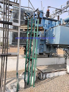
Neutral point or indirect earthing

2.Lighting arresters: The lighting arresters installed at substation should be earthed.The given below image shows the earthing system of lighting arrester:
3.Metal body of electric equipment: The metal body of all the electric equipment like transformers, circuit breakers, isolators, panels, tap-changer panel, distribution panel etc install at sub-station should be earthed.
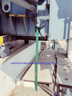
Metal body earthing
Metal body earthing

4.Metallic frames: All the frames (metallic structures) on which electric equipment install should be earthed.
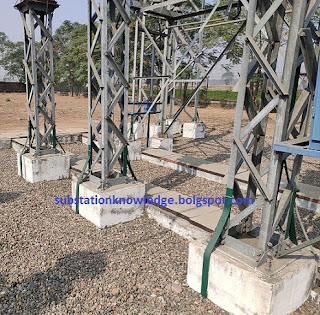
Metallic frame earthing

Practical value of earth resistance of substation equipment:
In given image the practical value of earth resistance is given below:
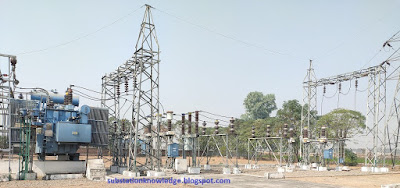
Substation Yard
Substation Yard
Power transformer body - 0.90 ohm
HV neutral - 0.90 ohm
LV neutral - 0.90 ohm
SF6 breaker - 0.31 ohm
Lighting arresters: R - 0.31 ohm  Y - 0.31 ohm  B - 0.30 ohm
Current transformer: R - 0.31 ohm  Y - 0.31 ohm  B - 0.30 ohm
These given value of earth resistance is in satisfactory range.Because this data is a medium power substation and value of earth resistance is less than 1.Less the value of earth resistance, more effective is the earthing.
The earth resistance measured by GROUND RESISTANCE METER or EARTH TESTER or OHM METER.
( In this type of instrument we have three electrodes and we hammer this electrodes in ground.Applying the voltage ( by meter battery) by meter between these electrodes.The current is flow in each electrodes.Thus by the value of current and voltage, meter shows the value of earth resistance with the help of OHM'S Law.
Mainly the current and voltage in each electrode same)

Conclusion: The final conclusion is that earthing of electric equipment is very necessary.Because it protect the life of man at the time of fault and also increase the life of the equipment.


CIRCUIT BREAKER OPERATION

WHAT IS CIRCUIT BREAKER AND BASIC PRINCIPAL?

Circuit Breaker: It is a device that close or open the electrical contact in a chamber (interrupter) in normal as well as abnormal (fault) condition.

OR

A device that isolate the electrical equipment (transformer, generator etc) by breaking the contact from faulty circuit.
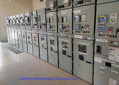
Circuit breaker panels
Basic principal of operation of circuit breaker:
The working principal of circuit breaker can be explain by given two parts:
1.Opening of contacts of circuit breaker
2.Extinguishing of arc produce between contacts.

Working diagram circuit breaker
1.Opening of contacts: The circuit breaker always connected in series with circuit.As shown in figure, circuit breaker has a moving contact in which one end is fixed and another end is movable.A handle is also attached with movable end.The circuit breaker can be operate manually or automatic.For automatic operation a device is connected with circuit breaker.
According to figure the trip coil is connected with current transformer and it is also connected with automatic operated device (for automatic operation of circuit breaker).In normal condition current flow from circuit.When the current above normal condition (at the time of fault), then current transformer excited and the increase current also flow in trip circuit.Thus trip coil energized and it attract the mechanical device and the handle connected with movable end move (as shown in figure) and it disconnect from fix end, thus it is break the circuit.

2.Extinguishing of arc: When the contact of circuit breaker opened, then a high current flow between contact, that produce spark and heat between the contact.Due this the air or oil between the contact ionized.Thus resistance between contact decreases and voltage drop across contact also decreases.Thus spark between the contact increases gradually.So, it is important to stop the arc at this time.Because if it persists for some time, it may be become more dangerous.

The extinguishing of arc in circuit breaker take place by given method:
1.High resistance method: In this method the arc is extinguish by increasing the resistance between contact.This method is used in low and medium voltage air circuit breaker.It is also used in DC circuit breakers.The following methods is used for increasing the resistance between contacts:
a) Reducing ionized particles: The ionization of air or oil depends upon the potential gradient and temperature between contacts.So, by decreasing the potential gradient and temperature between contact we can reduce the ionization of particles.We can reduce potential gradient by increasing the distance between contacts.By cooling the arc we can decrease the temperature between contacts.
b) Increasing the length of arc: We know that resistance is directly proportional to length.Thus by increasing the length between contacts.The length of produce arc increases.So, resistance between contact increases and it extinguish the arc.
c) Decreasing the cross section area of the arc: We know that resistance is inversely proportional to cross section area.So, by using thin contacts we can decrease the cross section area of arc.Thus the arc suppress easily.
d) Splitting the arc: By inserting conducting plates between produce arc.We can split the arc.Thus arc extinguishes easily.

2.Low resistance method: This method is used for AC circuit breakers only.Because in this method the arc is suppress at the time of zero condition of AC.Thus it does not re-strike to produce arc again.It is also know as ZERO POINT method.
In this method between the arc produces between contact is cooled by the acceleration of pressure free air or gas.So, the air or oil between the contact is not ionized by arc.
→This method is used for high capacity breakers.

Desired requirements in circuit breaker: The desired requirements in circuit breaker is given below.
1.Safety: It should be work properly in normal and abnormal condition.
2.Quickness: It should be work quickly.At the time of fault it should be break the faulty circuit quickly.
3.Selectivity: At the time of abnormal (fault) condition, it should be break the only faulty circuit without disturbing the normal circuits.
4.Reliability: It should be operate only in fault condition.
5.Sensitivity: It should be sensitive for fault.At the time of fault it should be operates quickly.

Duties of circuit breaker: The duties of circuit breaker is given below.
1.It should be work properly on full load (without rise the temperature).
2.It should be open and close on no load.
3.It should be operate at time of fault.
4.At normal condition, it should be open and close.

Conclusion: The final conclusion is that circuit breaker behaves like a switch as well as a protective device.With the help of circuit breaker we can open or close the circuit at normal condition and at time of fault it operates quickly and protect the electrical system.

Important links:

Coupon

Popular Posts