POWER FACTOR AND USE OF CAPACITOR BANK UNIT:
POWER FACTOR: a) The ratio of real power (KW) to apparent power (KVA) is known as power factor.
P.F. = real power/apparent power
b) It is also defined as cosine of angle between voltage and current.
The value of power factor cannot be more than one.
ADVANTAGES OF HIGH POWER FACTOR (NEAR TO 1):
1.If the power factor near to unity we obtain maximum power.
2.For fixed KVA the transformer KW capacity increases.
ex:for 20 KVA transformer KW value of transformer at p.f. 0.90=20*0.90 =18 KW
at p.f. 0.95 = 20*0.95 = 19 KW
3.Efficiency of transmission and distribution line increases.
4.Voltage drop reduces.Because load current decreases.
5.Improvement in voltage regulation.Because receiving end voltage increases upto some extent.
6.Electricity charges per unit (KWH) decreases.
DISADVANTAGES OF LOW POWER FACTOR:
Power consumed in a.c. circuit depends upon power factor.
Power consumed is given by:
P = √3V*I*cosθ
I = P/√3V*cosθ
For constant power P and voltage V current is inversely proportional to power factor.Thus is power factor is less than current will be high and vice versa.
The disadvantages of low power factor is given below:
1.Large copper losses: At low p.f. conductors have to carry large current.Thus I2R losses increases.
2.Conductor size increases: At low p.f. current increases,so carrying large current increase conductor size required.
3.KW output: For fixed KVA on decreasing p.f. output KW also decreases.
KW = KVA cosθ
4.Large KVA rating of equipment: The electrical machinery i.e. alternator, transformer are always rated in KVA.
KW/cosθ = KVA
At low p.f. KVA rating of equipment is more, making the equipment large in size.Hence the cost is increased.
5.Voltage drop: Due to high value of current voltage drop (IZ) increases.
6.Voltage regulation: Due to high voltage drop, voltage regulation become worst.
Causes of low power factor:
- Transformer: It draws a magnetizing current it lags with respect to e.m.f. at light load.But normal load it doesn't much effect the p.f.
- Induction motor: It works on same principle as transformer.It works on very poor p.f. when runs at no load.
- Arc lamp
- Furnace
- Electric welding etc.
METHOD OF POWER FACTOR IMPROVEMENT:
The main purpose of improvement of power factor to obtain maximum power.Because in capacitive circuit the power loss is zero i.e. current and voltage in phase.
1.Use of capacitor bank unit: This work on principal by supplying same amount of leading reactive power so that resultant of leading and lagging component of reactive power becomes zero.Thus p.f. become unity.
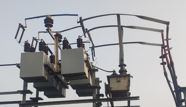
This is always connected in parallel with equipment.The capacitor bank can be connected in either star or delta.The given below image is star connected capacitor bank unit.
 |
| Capacitor Bank Unit |
- The value of load current decrease.
- The voltage increases up to some extent.
- Small losses.
- Require less maintenance.
- Less running cost.
The exact value of capacitors to be connected for improving the p.f. can be determined as follow:
ex: Let the load on 11 kV incomer of power transformer is 400 A and p.f. 0.90.If we want to correct p.f. up to 0.95.Than capacity of capacitor bank required find by given method:
initial p.f.(cosθ) = 0.90
final p.f.(cosθ) = 0.95
P = 11*400*0.90*1000 KW
θ1=cos inverse(0.90)=25.84 degree
θ2=cos inverse(0.95)=18.19 degree
tanθ1=tan(25.84) tanθ2=tan(18.19)
KVAR required = P(tanθ1-tanθ2)
= 11*400*0.90*1000{tan(25.84) -tan(18.19)}
= 3.9(0.48-0.32) MVAR
= 0.624 MVAR or 624 KVAR
Capacitor unit connected in each phase = 624/3 = 208 KVAR
Capacitor Bank Panel
In the panel of capacitor bank the value of reactive component of current is given by 79.2 A.
So leading reactive power (KVAR) = 79.2*11 KV = 0.872 MVAR
2.Use of synchronous condensers: Synchronous motor connected parallel to the system and it is run at no load to improving the p.f. of system.
An over excited synchronous motor,working at no load is used for power factor improvement.The word condenser is used because it draws leading current like a condenser.


No comments:
Post a Comment
Please do not use those type of word these hurt any people.