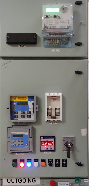
DIFFERENT ACCESSORIES MOUNTED ON CIRCUIT BREAKER PANEL AND ITS SUPPLY:
The different type of accessories that is mounted on circuit breaker and its supply is given below.The knowledge of supply of different accessories is very necessary because it is very helpful for checking and maintaining the accessories when it is faulty.These accessories mainly works on 230V AC or 220V DC/24 DC.So we discuss about the supply of different accessories one by one.
Firstly we discuss about indication lamps and push buttons that is shown in above image.
1.GREEN LAMP: If it glow it shows breaker in OFF condition means not in service.The supply given to green lamp is 230V AC.
2.RED LAMP: It is glow when breaker is ON condition means breaker is in service.The supply given to red lamp is 230V AC.
3.BLUE LAMP: If it glow it shows our circuit breaker spring charging motor is fully charged.The supply given to blue lamp is 230V AC.
4.WHITE: If it glows on pressing push button than our trip circuit healthy means DC supply is presence up to shunt trip coil of CB and CB trip at time of fault.The supply given to white (trip circuit healthy) lamp is 220V/24V DC.
5.AMBER: If it glows means breaker is auto trip due to fault on feeder.The supply given to amber (auto trip) lamp is 220/24V DC.
6.CLEAR: At the time of DC fail means DC supply is not in CB.Than clear (DC fail) lamp glow.The supply given to clear lamp is 230V AC.
7.BLACK COLOR PUSH BUTTON: After pre-close and post close of CB this button is used.By using this button white lamp glow means it indicate our trip circuit healthy.Thus this button is used for trip circuit healthy check.
8.YELLOW COLOR PUSH BUTTON: At time of fault CB trip and thus alarm bell operate that indicate the CB trip.To stop this alarm bell we will push yellow color button.
9.RED COLOR PUSH BUTTON: When alarm operate the relay of alarm bell also operate.To reset the alarm bell relay we push red color button.
10.BLUE COLOR PUSH BUTTON: This button is used to check the DC fail in CB.
SWITCHES: The given below switches mounted on CB panel:
1.T-N-C SWITCH: This switch is used to close or trip the circuit breaker.It has three position (Trip, neutral and close).This switch has pistol grip handle spring return to neutral means when we close or trip by the switch after operation switch handle comes to neutral.The supply given to switch is 220/24V DC.
2.TOGGLE SWITCH: There is two toggle switch mounted on CB panel.This switch is used for heater and spring charging motor.The supply given to toggle switch is 230V AC.
METERS: The given below meters mounted on CB panel:
1.Digital Voltmeter: This meter show the input voltage of the CB.Inbuilt selector switch is also present in this meter.With the help of this switch we can check line as well as phase voltage.The input supply given to this meter is 230V AC.
2.Digital Ammeter: This meter shows the output current(load) on the CB.With the help of inbuilt selector switch we can check line as well phase current.The input supply given to this meter is 230V AC.
(For more information see the topic digital ammeter and voltmeter reading setting topic in this site).
3.Power factor meter: This meter shows the power factor of the load.The supply given to this meter is 230V AC.
4.Solid state trivector meter: This meter given KWH, KVAH, KVAR reading of the load.The supply given to this meter is 110V (PT Secondary supply 110V).
BELL AND BUZZER:
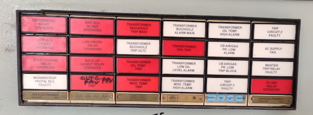
1.Bell/Hooter (Trip alarm): Bell is a tripping alarm means it will operate when breaker is trip.The input supply of bell is 220V/24V DC.Due to operation of given below relay CB trip and alarm/hooter operate.
1.HV restricted earth fault relay
2.Transformer Pressure release valve trip
3.Transformer winding temperature trip
4.Transformer oil temperature trip
5.Transformer buchholz trip main
6.On load tap changer (OLTC) PRV trip
7.Differential relay
8.O/C and E/F relay
9.Master trip relay
10.Back O/C and E/F relay operated
11.Over flux relay
Relay indication
2.Buzzer: It is a non tripping alarm means at this time breaker is in on condition (service).It operates when panel DC fail.The input supply given to buzzer is 230V AC.
3.Bell/hooter (Non-trip alarm): This bell/hooter operate at that time when CB is not trip.This alarm operate when given below relay will operate.
1.Transformer oil temperature high alarm
2.Transformer buchholz alarm main
3.Transformer low oil level alarm
4.Transformer winding temperature high alarm
5.AC supply fail relay
6.Faulty master trip relay
RELAYS: In this topic we only discuss about different relay input supply.In next topic we discuss one by one about the different relay.The supply given to different relay is given below:
1.Non directional IDMT relay (51+51N) O/C & E/F = 220V/24V DC
2.Restricted earth fault relay (REF) = 220V/24V DC
3.Sensitive earth fault relay = 220V/24V DC
4.Mater trip relay = 220V/24V DC
5.Inverse time under voltage, over voltage & Neutral displacement relay = 220V/24V DC
6.Time delay relay = 220V/24V DC
Important links:
different term regarding circuit breaker rating?
operating duty of circuit breaker?


No comments:
Post a Comment
Please do not use those type of word these hurt any people.