ELECTRICAL CIRCUIT AND PARTS OF AIR CONDITIONER
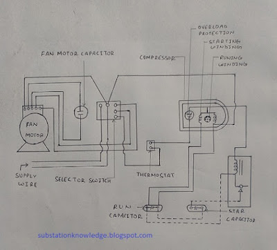
In electrical system of air conditioner different types of electrical components are used.The different components of electric system of air conditioner is given below, that is shown in figure:
 |
| Circuit diagram air conditioner |
a) Compressor motor
b) Fan motor
c) Starting capacitor
d) Running capacitor
e) Thermal overload protection
f) Main thermostate or temperature controller
g) Starting relay
h) Unit control switches
e) Fan capacitor
f) Motor compressor units
g) Connecting wire
The detail and working of above electrical components are given below:
1.Compressor motor and fan motor: In air conditioner unit two motors are used.These motors are single phase squirrel cage rotor, type induction motors.
The motor used for compressor motor is mainly capacitor start and capacitor run induction motor and the motor used for evaporator and condenser fan is capacitor start type induction motor.The speed of fan is controlled by induction regulator.
2.Starting capacitor: The starting capacitor provide starting torque to compressor motor and motor starts easily.It is connected to series in circuit.It is generally electrolytic capacitor.
3.Running capacitor: It is purely different from starting capacitor.It is heavy duly oil filled capacitor.It is always connected to series with compressor motor.
It improves the running characteristics of motor and also increases the starting torque of motor.It also increases the power factor, thus current taken by motor decreases (current is inversely proportional to power factor at constant voltage).Thus electrical energy consumption by motor decrease and makes the system economical.
4.Starting relay: This is single phase relay and works on single phase supply.The starting relay coil is always connected in series with running winding of motor.At the time of starting, motor takes high current from supply, thus the contact of relay closed and starting winding of motor and starting capacitor connected with each other and motor starts working.
When the motor speed increase, the value of current in running winding decrease.Thus the contact of relay become open and starting capacitor disconnect from circuit and running capacitor always connected to motor.
The starting relays are two types:
- Voltage type relay
- Current type relay
6.Thermostate or temperature controller: This works on desire room temperature.When the room temperature increases, it closes the compressor circuit and compressor motor starts working.
When the temperature decrease, it break the compressor circuit and compressor motor does not work.Thus it control the room temperature.
7.Unit control switch:This switch is situated at the cabinet.This switch may be knob or rotary type.This switch has four conditions, that is marked by OFF-FAN-COOL-OPEN.
Conclusion: Thus final conclusion is that, the knowledge of electric circuit diagram and component of air conditioner is necessary.Because it helps at the time of maintenance and repairing of air conditioner.
Important link:


No comments:
Post a Comment
Please do not use those type of word these hurt any people.