- 7ACAF469539AE5BE731ED4CC5FA1B148

Amazon

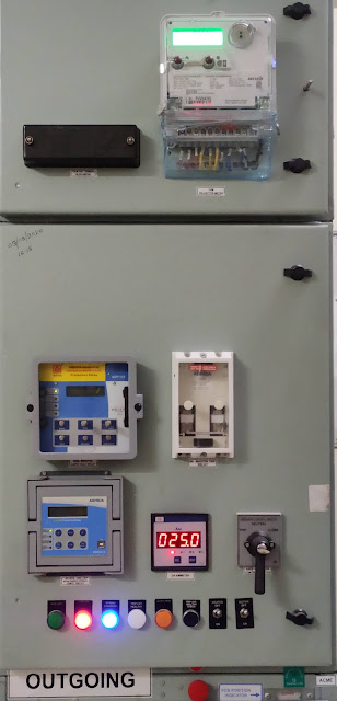
ACCESSORIES AT CIRCUIT BREAKER PANEL

DIFFERENT ACCESSORIES MOUNTED ON CIRCUIT BREAKER PANEL AND ITS SUPPLY:

The different type of accessories that is mounted on circuit breaker and its supply is given below.The knowledge of supply of different accessories is very necessary because it is very helpful for checking and maintaining the accessories when it is faulty.These accessories mainly works on 230V AC or 220V DC/24 DC.So we discuss about the supply of different accessories one by one.

Circuit breaker panel
Circuit Breaker Panel

Firstly we discuss about indication lamps and push buttons that is shown in above image.

1.GREEN LAMP: If it glow it shows breaker in OFF condition means not in service.The supply given to green lamp is 230V AC.

2.RED LAMP: It is glow when breaker is ON condition means breaker is in service.The supply given to red lamp is 230V AC.

3.BLUE LAMP: If it glow it shows our circuit breaker spring charging motor is fully charged.The supply given to blue lamp is 230V AC.

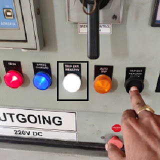
4.WHITE: If it glows on pressing push button than our trip circuit healthy means DC supply is presence up to shunt trip coil of CB and CB trip at time of fault.The supply given to white (trip circuit healthy) lamp is 220V/24V DC.

5.AMBER: If it glows means breaker is auto trip due to fault on feeder.The supply given to amber (auto trip) lamp is 220/24V DC.

6.CLEAR: At the time of DC fail means DC supply is not in CB.Than clear (DC fail) lamp glow.The supply given to clear lamp is 230V AC.

7.BLACK COLOR PUSH BUTTON: After pre-close and post close of CB this button is used.By using this button white lamp glow means it indicate our trip circuit healthy.Thus this button is used for trip circuit healthy check.

8.YELLOW COLOR PUSH BUTTON: At time of fault CB trip and thus alarm bell operate that indicate the CB trip.To stop this alarm bell we will push yellow color button.

9.RED COLOR PUSH BUTTON: When alarm operate the relay of alarm bell also operate.To reset the alarm bell relay we push red color button.

10.BLUE COLOR PUSH BUTTON: This button is used to check the DC fail in CB.

SWITCHES: The given below switches mounted on CB panel:

1.T-N-C SWITCH: This switch is used to close or trip the circuit breaker.It has three position (Trip, neutral and close).This switch has pistol grip handle spring return to neutral means when we close or trip by the switch after operation switch handle comes to neutral.The supply given to switch is 220/24V DC.

2.TOGGLE SWITCH: There is two toggle switch mounted on CB panel.This switch is used for heater and spring charging motor.The supply given to toggle switch is 230V AC.

METERS: The given below meters mounted on CB panel:

1.Digital Voltmeter: This meter show the input voltage of the CB.Inbuilt selector switch is also present in this meter.With the help of this switch we can check line as well as phase voltage.The input supply given to this meter is 230V AC.

2.Digital Ammeter: This meter shows the output current(load) on the CB.With the help of  inbuilt selector switch we can check line as well phase current.The input supply given to this meter is 230V AC.

(For more information see the topic digital ammeter and voltmeter reading setting topic in this site).

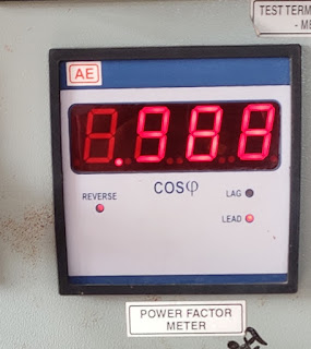
3.Power factor meter: This meter shows the power factor of the load.The supply given to this meter is 230V AC.

4.Solid state trivector meter: This meter given KWH, KVAH, KVAR reading of the load.The supply given to this meter is 110V (PT Secondary supply 110V).

BELL AND BUZZER:

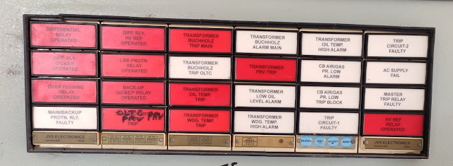
1.Bell/Hooter (Trip alarm): Bell is a tripping alarm means it will operate when breaker is trip.The input supply of bell is 220V/24V DC.Due to operation of given below relay CB trip and alarm/hooter operate.

1.HV restricted earth fault relay

2.Transformer Pressure release valve trip

3.Transformer winding temperature trip

4.Transformer oil temperature trip

5.Transformer buchholz trip main

6.On load tap changer (OLTC) PRV trip

7.Differential relay

8.O/C and E/F relay

9.Master trip relay

10.Back O/C and E/F relay operated

11.Over flux relay

Relay indication

Relay indication

2.Buzzer: It is a non tripping alarm means at this time breaker is in on condition (service).It operates when panel DC fail.The input supply given to buzzer is 230V AC.

3.Bell/hooter (Non-trip alarm): This bell/hooter operate at that time when CB is not trip.This alarm operate when given below relay will operate.

1.Transformer oil temperature high alarm

2.Transformer buchholz alarm main

3.Transformer low oil level alarm

4.Transformer winding temperature high alarm

5.AC supply fail relay

6.Faulty master trip relay

RELAYS: In this topic we only discuss about different relay input supply.In next topic we discuss one by one about the different relay.The supply given to different relay is given below:

1.Non directional IDMT relay (51+51N) O/C & E/F = 220V/24V DC

2.Restricted earth fault relay (REF) = 220V/24V DC

3.Sensitive earth fault relay = 220V/24V DC

4.Mater trip relay = 220V/24V DC

5.Inverse time under voltage, over voltage & Neutral displacement relay = 220V/24V DC

6.Time delay relay = 220V/24V DC


Important links:

different term regarding circuit breaker rating?

operating duty of circuit breaker?


TRANSFORMER

 WHAT IS TRANSFORMER? RATIO OF TRANSFORMER? TERM IN RATING PLATE OF TRANSFORMER?
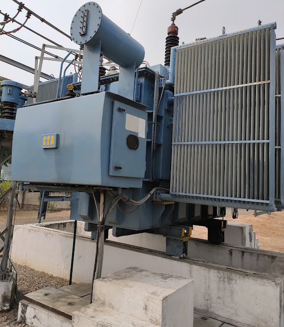
TRANSFORMER: It is a static device,which work on principal of static and mutual induction and transforms a.c. power from one voltage to other voltage without change in frequency.

The emf equation of transformer is given below:

E1 = 4.44fϕN1 volt

E2 = 4.44fϕN2 volt

E1 = Primary side emf

E2 = Secondary side emf

f = frequency

ϕ = maximum value of flux

N1 = primary side number of turns

N2 = secondary side number of turns


Transformer
Transformer

Ratio of transformer is given below:

1.Voltage Ratio: It is the ratio of secondary voltage to primary voltage.

K = V2/V1

For step up transformer, V2>V1, K>1

For step down transformer, V2<V1, K<1

2.Turn Ratio: It is the ratio of primary turns to secondary turn.

Turn ratio = N1/N2

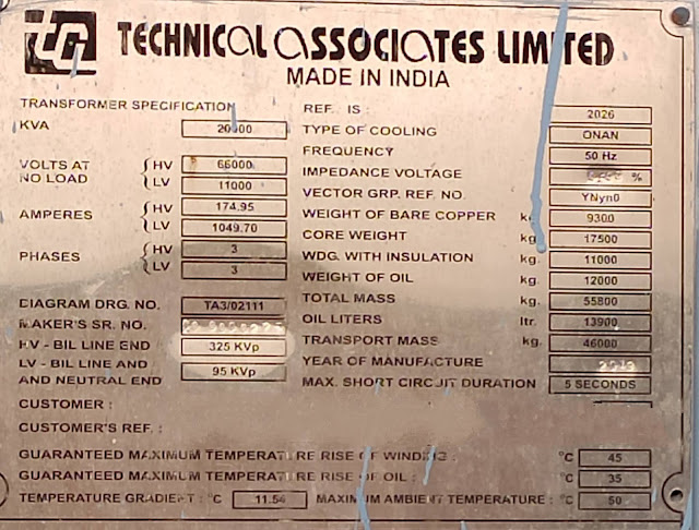
Rating: The rating plate of transformer shown below.

Power transformer rating plate

Rating plate transformer

The meaning of different term in rating plate is given below:
1.Capacity of transformer: The transformer capacity is always in KVA rating because the copper loss depends upon current and core loss depends upon voltage means total losses in transformer depends upon voltage ampere product.Thus rating does not depend upon power factor.So it is always in KVA rating.In given rating plate the rating of transformer is 20 MVA

2.Voltages at no load: It is that voltage when transformer in service but load at transformer is zero.
In given rating plate high voltage side (HV) is 66 KV and Low voltage side (LV) is 11 KV.

3.Amperes: It is that maximum value of current at which transformer works satisfactory above this value of current the winding of transformer may be burn and may be any other electrical and structural damage occurs.In given rating pate the primary side current (HV) is 174.95 A and secondary side (LV) current is 1049.70 A.

4.BIL (basic insulation level) line end voltage: It is that value of voltage that transformer withstand without any damage of insulation at the time of impulse voltage (lighting,surge voltage etc).In given rating plate the HV side BIL is 375 KVp and LV side and neutral side BIL is 95 KVp.

5.Type of cooling: It is the method that is used for transformer cooling.In given rating plate oil natural air natural (ONAN) type cooling is used.

6.Frequency: The rated frequency is that on which transformer is designed to work.In rating plate the frequency is 50 Hz.It is the standard frequency in India.

7.Vector group (YNyn0) and number of phase: This vector group show that transformer is star-star transformer means HV side as well as LV side is transformer connected and this type of power transformer two NCT is connected from both side neutral.In given rating plate 3 phase is shown means this transformer is 3 phase transformer.

8.Weight of bare copper and with insulation: The rating plate also give information about weight of bare copper winding and with insulation.in given rating plate bare copper weight is 9300 kg and with insulation weight is 11000 Kg.

9.Core weight: The core of the transformer is that on which transformer is situated.In given rating plate the core weight is 17500 Kg.

10.Weight of oil and liters: It the weight of transformer oil in kg and liters that is filled in transformer.
In given rating plate weight is 1200 kg and 13900 liters.

11.Transport mass: It is total mass of transformer.In given rating plate is 46000 kg.

12.Max short current duration: It is the time which can transformer withstand at the time of short circuit current (generally 25 times the rated current) on secondary side.In given rating plate it is 5 sec.

13.Ambient temperature: The average temperature of transformer is known as ambient temperature.In given plate it is given 50 degree celsius,means average of 24 hours temperature of transformer does not exceed 50 degree celsius.


OPERATION AND INSTRUCTIONS OF FIRE EXTINGUISHER

WHAT IS THE METHOD OF OPERATION AND GENERAL INSTRUCTION OF FIRE EXTINGUISHER?

Method of operation of fire extinguisher: 


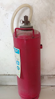
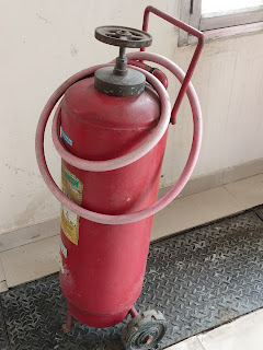
Fire Extinguisher
Fire Extinguisher

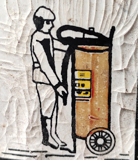
Fire Extinguisher operation chart
 Fire Extinguisher operation chart

The operation of given above fire extinguisher is given below:
  1. Firstly shake it.
  2. Keep vertically as shown in image.
  3. Remove the safety clip that is situated near the knob of cylinder.
  4. Than strike hard on knob.
  5. Keep the jet to the base of fire and swipe side to side.

Fire Extinguisher operation

The operation of above shown fire extinguisher is given below:
1.Keep vertically as shown in image and uncoil the pipe of cylinder.
2.Remove the safety clip.

Fire Extinguisher operation

3.Hold the pipe in hand and shake the cylinder.
4.Than open the wheel of cap.

Fire Extinguisher operation

4.Now keep the extinguisher horizontally and aim the jet to the base of fire.

Fire Extinguisher operation


 General instructions for fire extinguisher:
1.The fire extinguisher should be ISI marked.
2.Daily or routine inspection is necessary.
a).The seal and temperature indicator are not missing and broken.
b).It is full (by weighting and lifting).
c).It is not corroded.
d).It is not damage.
e).It has no leaking or has clogged nozzles.
3.It should be refill after the expiry date.
4.Preventive maintenance is necessary.
a).Care and maintain as per ISI rule.
5.The extinguisher is used according to the type of fire.
6.Fire of oil should not be exinguished by water.
7.At the time of fire extinguishing if you feel uncomfortable,than keep away from fire place.
8.There should be training of staff for fire extinguishing at some interval of time.
9.Fire extinguishing should be start from one place and go ahead by extinguishing the fire.
10.At the time of fire extinguishing wear all the safety equipment (like helmet,safety dress,shoes,gloves etc).

CONCEPT OF POWER AND CURRENT

POWER AND CURRENT OF ELECTRICAL EQUIPMENT:

1.Definition of true power (KW) and formula:

True Power: It is the product of current,voltage and power factor (depends upon the nature of load inductive, capacitive, resistive).

OR

The rate of transfer of electrical energy per unit time is known as power.

Its unit is watt.

P = Electrical energy (KWH) / time(t)


Power rating: The maximum power (product of voltage,current and power factor) on which the equipment works normally.

 P = √3V*I*cosθ

V=Line voltage

I=Line current

ex: Let a power transformer (primary side = 66 KV and secondary side = 11 KV) current on secondary side is 500A at power factor 0.95.Thus output power of transformer find by given formula:

P = √3V*I*cosθ

√3*11*500*0.95*1000

= 9.04 MW

Thus output power of this transformer at load current 500 A, 11 KV at p.f. 0.95 is 9.04 MW.

2.Definition of Apparent power (KVA) and formula:

Apparent power (KVA): It is the product of current and voltage.Its unit is VA.

Apparent power (VA) rating: VA rating of an equipment is that on which it works normally.

From above given example: P = 9.04 MW and p.f. = 0.95

The VA rating of transformer find by given formula:

P/cosθ = VA

9.04 MW/0.95 = VA

= 9.5 MVA

 Thus capacity of transformer = 9.5 MVA

3.Definition of current and formula:

Current: The rate of flow of charge (mainly electron) is known as electric current.

                                 I = Q/t

Q = charge

t = time

Its unit is ampere.

Ampere: If one coulomb charge flow for one second, then it is known as one ampere. 

Current rating: The maximum consumption of current by an equipment on which it works normally.

                              I = P/√3V*cosθ

exLet a power transformer (primary side = 66 KV and secondary side = 11 KV) has rating 1 MVA.Then by using above formula we can find the value of current primary side as well as secondary side.

The value of current on primary side is given below:

I = 1 MVA/√3*66 KV*1

=8.75 A

Similarly on secondary side is:

I = 1 MVA/√3*11 KV*1

=52.5 A

The given chart give the value of current of different rating of power transformers:


Transformer current rating


CONCEPT OF POWER FACTOR

 POWER FACTOR AND USE OF CAPACITOR BANK UNIT:

POWER FACTOR: a) The ratio of real power (KW) to apparent power (KVA) is known as power factor.

P.F. = real power/apparent power

b) It is also defined as cosine of angle between voltage and current.

The value of power factor cannot be more than one.

ADVANTAGES OF HIGH POWER FACTOR (NEAR TO 1):

1.If the power factor near to unity we obtain maximum power.
2.For fixed KVA the transformer KW capacity increases.
ex:for 20 KVA transformer KW value of transformer at p.f. 0.90=20*0.90 =18 KW

 at p.f. 0.95 = 20*0.95 = 19 KW

3.Efficiency of transmission and distribution line increases.

4.Voltage drop reduces.Because load current decreases.

5.Improvement in voltage regulation.Because receiving end voltage increases upto some extent.

6.Electricity charges per unit (KWH) decreases.

DISADVANTAGES OF LOW POWER FACTOR:

Power consumed in a.c. circuit depends upon power factor.

Power consumed is given by:

P = √3V*I*cosθ

I = P/√3V*cosθ

For constant power P and voltage V current is inversely proportional to power factor.Thus is power factor is less than current will be high and vice versa.

The disadvantages of low power factor is given below:

1.Large copper losses: At low p.f. conductors have to carry large current.Thus I2R losses increases.

2.Conductor size increases: At low p.f. current increases,so carrying large current increase conductor size required.

3.KW output: For fixed KVA on decreasing p.f. output KW also decreases.

KW = KVA cosθ

4.Large KVA rating of equipment: The electrical machinery i.e. alternator, transformer are always rated in KVA.  

                               KW/cosθ = KVA

At low p.f. KVA rating of equipment is more, making the equipment large in size.Hence the cost is increased.

5.Voltage drop: Due to high value of current voltage drop (IZ) increases.

6.Voltage regulation: Due to high voltage drop, voltage regulation become worst.

Causes of low power factor:  

  1. Transformer: It draws a magnetizing current it lags with respect to e.m.f. at light load.But normal load it doesn't much effect the p.f.
  2. Induction motor: It works on same principle as transformer.It works on very poor p.f. when runs at no load.
  3. Arc lamp
  4. Furnace
  5. Electric welding etc.

METHOD OF POWER FACTOR IMPROVEMENT:

The main purpose of improvement of power factor to obtain maximum power.Because in capacitive circuit the power loss is zero i.e. current and voltage in phase.

1.Use of capacitor bank unit: This work on principal by supplying same amount of leading reactive power so that resultant of leading and lagging component of reactive power becomes zero.Thus p.f. become unity.

This is always connected in parallel with equipment.The capacitor bank can be connected in either star or delta.The given below image is star connected capacitor bank unit.

Capacitor bank unit
Capacitor Bank Unit
Advantages:

  1. The value of load current decrease.
  2. The voltage increases up to some extent.
  3. Small losses.
  4. Require less maintenance.
  5. Less running cost.

The exact value of capacitors to be connected for improving the p.f. can be determined as follow:

ex: Let the load on 11 kV incomer of power transformer is 400 A and p.f. 0.90.If we want to correct p.f. up to 0.95.Than capacity of capacitor bank required find by given method:

initial p.f.(cosθ) = 0.90

final p.f.(cosθ) = 0.95 

P = 11*400*0.90*1000 KW

θ1=cos inverse(0.90)=25.84 degree         

 θ2=cos inverse(0.95)=18.19 degree

tanθ1=tan(25.84)                                        tanθ2=tan(18.19)

KVAR required = P(tanθ1-tanθ2)

                         = 11*400*0.90*1000{tan(25.84) -tan(18.19)}

                                = 3.9(0.48-0.32) MVAR

                                = 0.624 MVAR or 624 KVAR

Capacitor unit connected in each phase = 624/3 = 208 KVAR

capacitor panel

Capacitor Bank Panel

In the panel of capacitor bank the value of reactive component of current is given by 79.2 A.

So leading reactive power (KVAR) = 79.2*11 KV = 0.872 MVAR

2.Use of synchronous condensers: Synchronous motor connected parallel to the system and it is run at no load to improving the p.f. of system.

An over excited synchronous motor,working at no load is used for power factor improvement.The word condenser is used because it draws leading current like a condenser.


DIGITAL VOLTMETER READING SETTING

 HOW TO VIEW AND EDIT SETTING OF DIGITAL PROGRAMMABLE VOLTMETER:

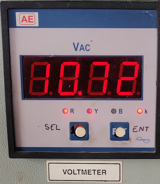
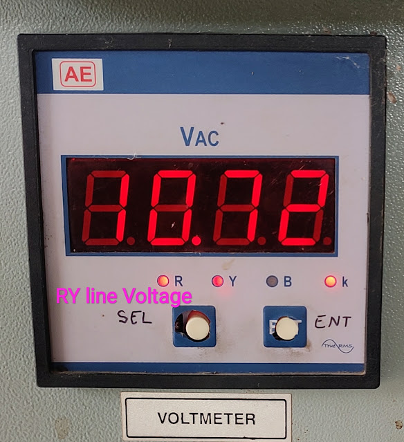
In digital voltmeter there is 2 button and 4 indication lights.


Voltmeter reading
Voltmeter reading

BUTTON:
1.SEL - Selector
2.ENT - Enter

INDICATION LIGHT:
1.R - Red phase
2.Y - Yellow phase
3.B - Blue phase
4.k - thousand

Similarly,
1.RY - RY line voltage
2.YB - YB line voltage
3.RB - RB line voltage

STEPS OF EDIT AND SETTING OF DIGITAL VOLTMETER:

SEL KEY: By pressing the SEL key we can check the voltage of each phase (R,Y,B) as well as line voltage (RY,YB,RB).

Voltmeter reading
Voltmeter reading

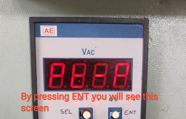
ENT KEY: By pressing ENT key we see the programmable mode of digital voltmeter.

PT PRIMARY VALUE VIEW AND EDIT:
First time pressing ENT meter shows PT-P (P.T. primary).

Voltmeter reading
Voltmeter reading


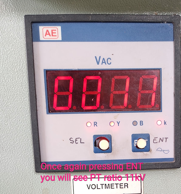
Once again pressing ENT key we will see primary side PT ratio.

Voltmeter reading
Voltmeter reading

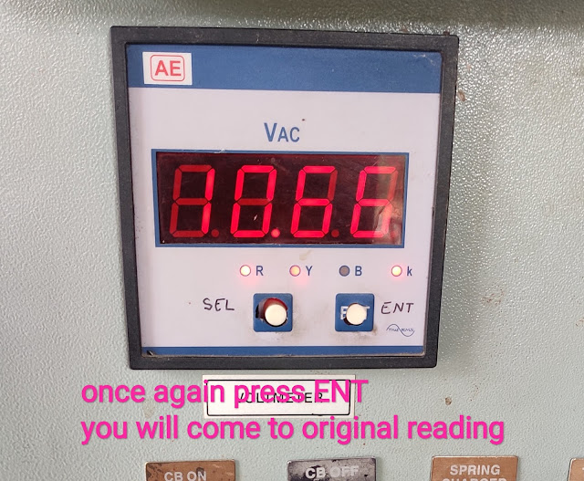
Now by pressing ENT we can scroll on digits and by pressing SEL key we can change the PT primary side value and after the setting of PT value,press the ENT key and back to default display.

Voltmeter reading
Voltmeter reading

PT SECONDARY VALUE VIEW AND EDIT:
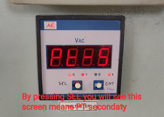
Press ENT key we will see PT primary side value and than press SEL key we will see the display as show in image (PT secondary).

Voltmeter reading
Voltmeter reading

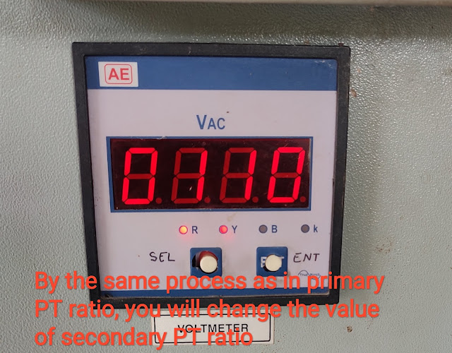
Once again pressing ENT key we will see the PT secondary value.

Voltmeter reading
Voltmeter reading

By pressing ENT key we can scroll on digits and by pressing SEL key we can change the value of PT secondary and after setting the PT secondary value,press the ENT key and back to default display.

Voltmeter reading
Voltmeter reading

Important links:


TYPES OF FIRE EXTINGUISHERS

 TYPES OF FIRE EXTINGUISHERS:

FIRE EXTINGUISHER: The equipment that is used for fire extinguishing is known as fire extinguisher.These are different type like chemical type, mechanical type etc.

These are used in factory,mill,substation,shopping mall,cinema hall,laboratory etc for fire extinguishing.

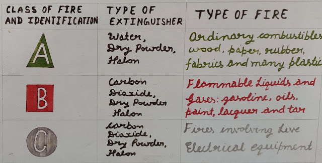
The different type of fire extinguisher is given below:

Fire class chart
Fire class chart

1.CLASS-A FIRE: These fire include fire of wood, forest, crops, paper, rubber, cloth etc.These type of fire is also known as dry fire. 

Class A fire
Class A fire

These type of fire extinguish by given below fire extinguisher:

a) Water type: In this type the extinguishing material is water.It lower the temperature of fire and thus it extinguishing the fire.

b) Dry Powder: In this type the extinguishing material is soda acid.It makes a layer on fire thus contact between fire and air (oxygen) vanishes thus it extinguish the fire.

c) Halon: It is a liquified, compressed gas that extinguish the fire.

2.CLASS - B FIRE: These fire include fire of transformer oil, CT oil, PT oil, circuit breaker oil fire, diesel, petrol etc.These are also known as oil lubricant fire.

Class B fire
Class B fire

These type of fire extinguish by given below fire extinguisher:

a) Chemical foam type: In this type of extinguisher the extinguishing material is foam produced by carbon dioxide gas.It covers the fire and lower the temperature of fire thus extinguishing the fire.

Some cases dry powder,halon fire extinguisher also used in class-b fire.

3.CLASS - C FIRE: These type of fire include fire of generator,motor,transformer winding,domestic and power wiring fire, wire insulation, control panel wiring fire etc.

Class C fire
Class C fire

These type of fire extinguish by given below fire extinguisher:

a) Carbon dioxide gas cylinder: In this type of extinguisher the extinguishing material is carbon dioxide.

b) Carbon tetra chloride fire cylinder: In this type of extinguisher the extinguishing material is carbon tetra chloride it produce phosgene gas that extinguish the fire.

MULTIPLYING FACTOR

WHAT IS MULTIPLYING FACTOR AND ITS FORMULA? 

MULTIPLYING FACTOR: Multiplying factor of meter is that parameters by virtue of which we use small scaled meter to get the reading up to multiplication factor times.

Now we will see the multiplying factor formula of different electrical meter:

1.FOR ENERGY METER: The given below formula used for finding the multiplying factor of energy meter.
M.F. = Connected CTR*Connected PTR  *1000
            Meter CTR*Meter PTR

The given term in formula is explained below.

a) Connected CTR: The ratio of Current transformer (CT) that is connected to panel (circuit breaker).

Panel PT ratio
Panel CT ratio

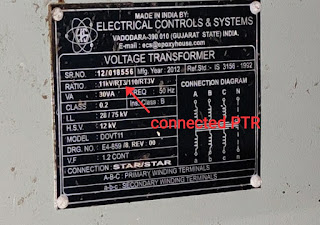
b) Connected PTR: The ratio of connected potential transformer or voltage transformer (PTR) that is connected to the panel (circuit breaker).

Panel PT ratio
Panel PT ratio

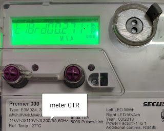
c) Meter CTR: The CT ratio of connected meter.

Meter CT ratio
Meter CT ratio

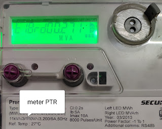
d) Meter PTR: The PT ratio of connected meter.

Meter PT ratio
Meter PT ratio

By using above formula and data we can find the value of multiplying factor of energy meter.
For example in give images:
Connected CTR= 200/5
Connected PTR= 11 kV/110 V
Meter CTR= 200/5
Meter PTR= 11 kV/110 V
So multiplying factor of this energy meter is:

M.F. = 200/5*11 kV/110 V *1000
            200/5*11 kV/110 V
        = 1000
Multiplying factor of the above energy meter is 1000.

Now we can use above formula for any value of  panel CTR & PTR and meter CTR & PTR to get the multiplying factor of energy meter.

2.AMMETER MULTIPLYING FACTOR: The ratio of circuit current (current to be measured) to the current taken by meter is known as "multiplying factor" of ammeter.
I = the current to be measured (I>Im)
Im = the current through meter.
M.F. = I/Im

3.VOLTMETER MULTIPLYING FACTOR: The ratio of voltage to be measured (circuit voltage) and the voltage across the meter is known as "multiplying factor" of voltmeter.
V = the voltage measured (V>v)
v = the voltage drop across the meter.
M.F. = V/v

4.WATTMETER MULTIPLYING FACTOR: The same formula of energy meter multiplying factor is used for find the multiplying factor of wattmeter.


WORK OF SUB STATION OPERATOR

SUB STATION ATTENDANT / SUB STATION OPERATOR WORK:

After joining duty:
1.Mark the attendance in log sheet.

Log sheet
Log sheet

2.Check the substation yard (NCT, CT, PT ,ISOLATOR ETC).
3.Check the DC battery charger is in ON condition.

battery charger panel
Battery Charger Panel

4.Check DC of C&R panel for trip (protection) circuit healthy.

indication lamps of circuit breaker

Indication lamps of circuit breaker

5.Check DC of Circuit breaker for trip (protection) circuit healthy.

trip circuit healthy push button

Trip circuit healthy push button

6.Check the HT side panel voltage.The voltage variation on this meter should be +_10% (up to 220 KV).

digital voltmeter
Digital voltmeter HT side

7.Check the 11kV incomer side voltage.The voltage variation on incomer side should be in the range of +_10%.

Digital voltmeter LT side

8.Check the power factor.The range of power factor should be in between 0.95 to 1.

digital power factor meter
Digital power factor meter

Amazon services
9.Check the frequency of the supply.The variation in frequency should be +_3%.

frequency indicator
Frequency indicator

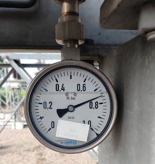
10.Check the SF6 gas pressure.The SF6 gass pressure range should be 5.5 to 8.

SF6 gas pressure indicator
SF6 Gas pressure indicator

11.Note the load of outgoing feeder in log sheet after the interval of 1 hour.
12.Check the transformer oil and winding temperature after the interval of 1 hour and note it in the log sheet.
oil and winding temperature indicator
Oil and Winding temperature indicator

13.Check the OLTC panel and tap position of transformer.
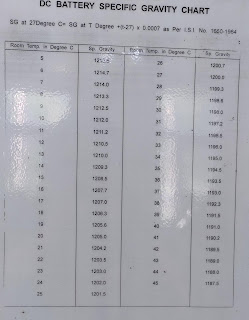
14.Check the battery room temperature and gravity and voltage of cells, the value of gravity of cell should be in the range that is shown in image.

DC batter gravity chart

15.Check the message book.
16.Check the permit book.
17. Issue permit on feeder to authorized person. 
18.Check the schedule timing of feeders and also record the data of tripping and breakdown.
19.Record the data of daily energy consumption (KWH reading).
20.At night inspect the yard and note the hot point of equipment if present in yard.
21.Attend the phone call of senior officer and power controller(P/C).
22.Check the cleanliness of substation. 

DUTY CYCLE OF CIRCUIT BREAKER

WHAT IS OPERATING DUTY CYCLE OF CIRCUIT BREAKER? 

Operating duty of circuit breaker terms related to opening, closing sequence of circuit breaker.
We always see a term on circuit breaker rating plate operating duty and it is written as:

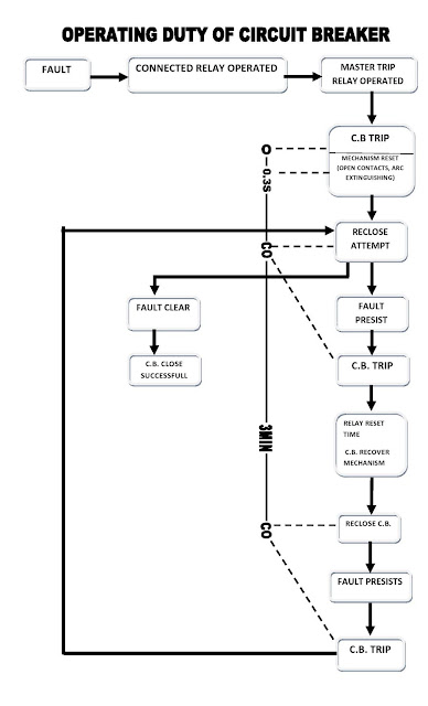
OPERATING DUTY:  O-0.3 sec-CO-3 min-CO
O: OPEN
C: CLOSE


Time sequence of operating duty of CB

The above terms relate the opening,closing sequence of circuit breaker.

Operating duty chart of CB
                                             
According to above diagram if fault occur on feeder than the relay connected on circuit breaker operated and at that time master trip relay operated and it trip (open) the breaker.
          And after 0.3 sec we can re-close the CB (circuit breaker):
1.If fault clear than closing of CB is successful.
2.If fault present at feeder CB trips instantly means re-closing of CB is unsuccessful.
This 0.3 sec is the time taken by the CB to recovering mechanism (contact open in chamber,arc extinguishing in chamber).


According to duty cycle after 3 minute we take second try(re-closing of CB),this is the relay reset time and breaker mechanism recover time.
If fault persists than circuit breaker relays operate and trip the circuit breaker instantly and this sequence follow for the smooth operation of circuit breaker and next re-closings done after 3 minutes as shown in diagram.

The knowledge of operating duty cycle of circuit breaker is very necessary.The following advantages of knowledge of operating duty cycle given below:
1.It increase the life period circuit breaker.
2.Reduce the maintenance cost.
3.Reduce any electrical and structure damage of CB.
4.Increases the life period of relay.

Important links:

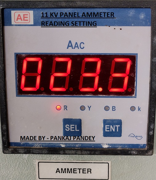
DIGITAL AMMETER READING SETTING

DIGITAL AMMETER READING SETTING:

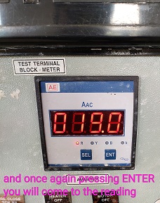
In  digital ammeter there is 2 button and 4 indication light.

digital ammeter reading setting
Digital ammeter reading 


BUTTON:
1.SEL - Selector
2.ENT - Enter

INDICATION LIGHT:
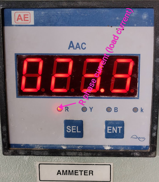
1.R - Red phase
2.B - Blue phase
3.Y - Yellow phase
4.k - thousand

STEPS OF EDIT AND SETTING OF DIGITAL AMMETER:

SEL KEY: By pressing the SEL key we can check the current of each phase (R,Y,B).


Digital ammeter reading setting
Digital ammeter reading 


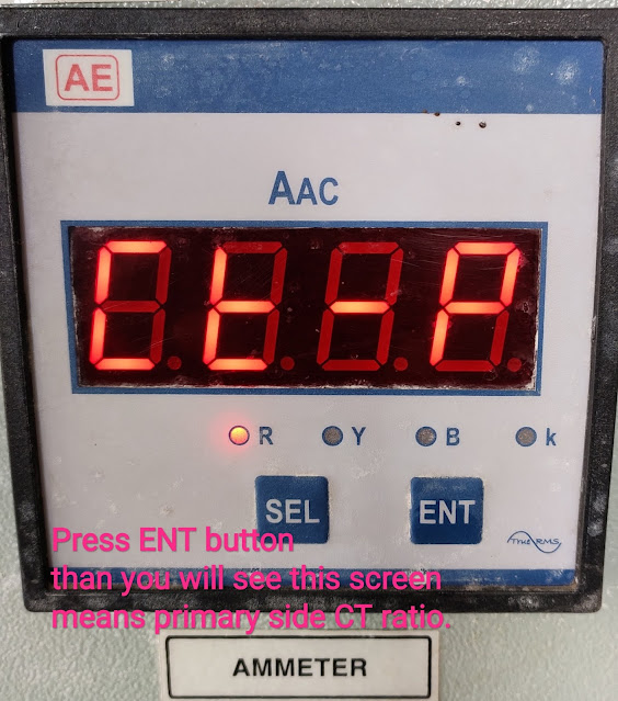
ENT KEY: By pressing ENT key we see the programmable mode of digital ammeter.

CT PRIMARY VALUE VIEW AND EDIT:
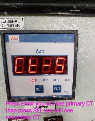
First time pressing ENT meter shows CT-P (C.T. primary).


Digital ammeter reading setting
Digital ammeter reading

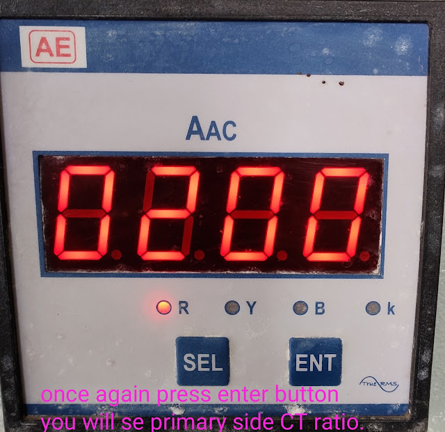
Once again pressing ENT key we will see primary side CT ratio.


Digital ammeter reading setting
Digital ammeter reading


Now by pressing ENT we can scroll on digits and by pressing SEL key we can change the CT primary side value and after the setting of CT value,press the ENT key and back to default display.


Digital ammeter reading setting
Digital ammeter reading


CT SECONDARY VALUE VIEW AND EDIT:
Press ENT key we will see CT primary side value and than press SEL key we will see the display as show in image (CT secondary).


Digital ammeter reading setting
Digital ammeter reading 


Once again pressing ENT key we will see the CT secondary value.


Digital ammeter reading setting
Digital ammeter reading

By pressing ENT key we can scroll on digits and by pressing SEL key we can change the value of CT secondary and after setting the CT secondary value,press the ENT key and back to default display.


Digital ammeter reading setting
Digital ammeter reading

Important links:


Coupon

Popular Posts